12/18/2025 11:11 a.m.
http://34.77.62.133/en/products/planet-converter-ethernet-to-vdsl2-profile-17th-telephone-cable-MD071/
http://34.77.62.133/en/products/planet-converter-ethernet-to-vdsl2-profile-17th-telephone-cable-MD071/
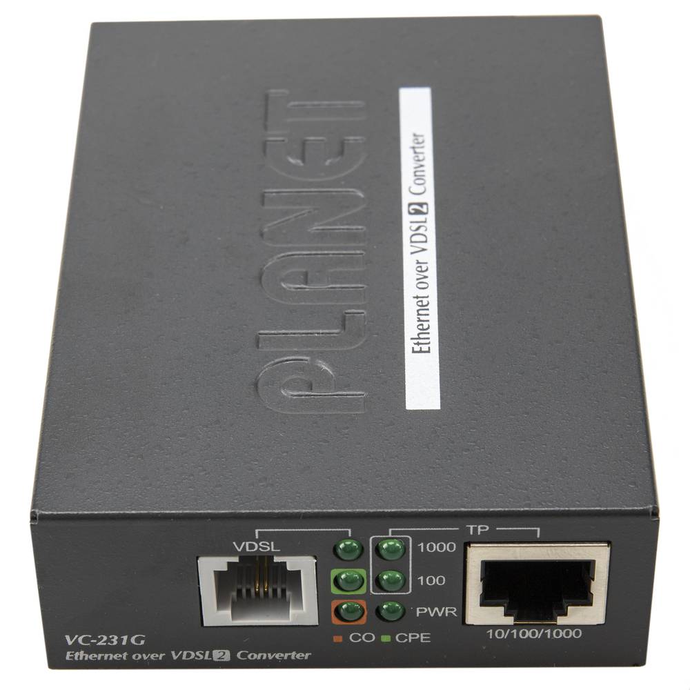
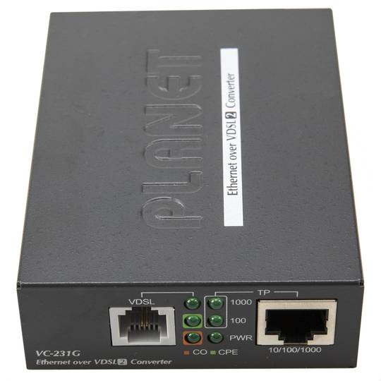
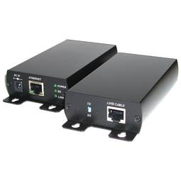
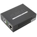
Planet Converter Ethernet to VDSL2 profile 17th (Telephone Cable)
REF: MD071
Specifications
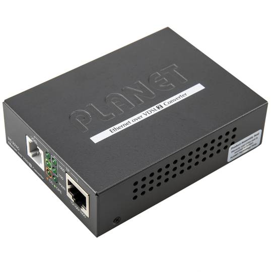
- LAN TCP / IP 10/100 Mbps to VDSL2 converter
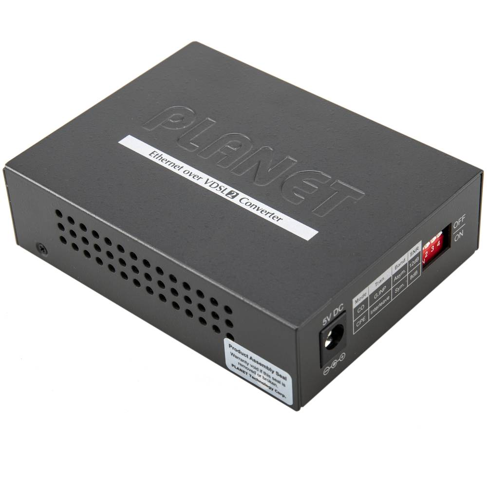
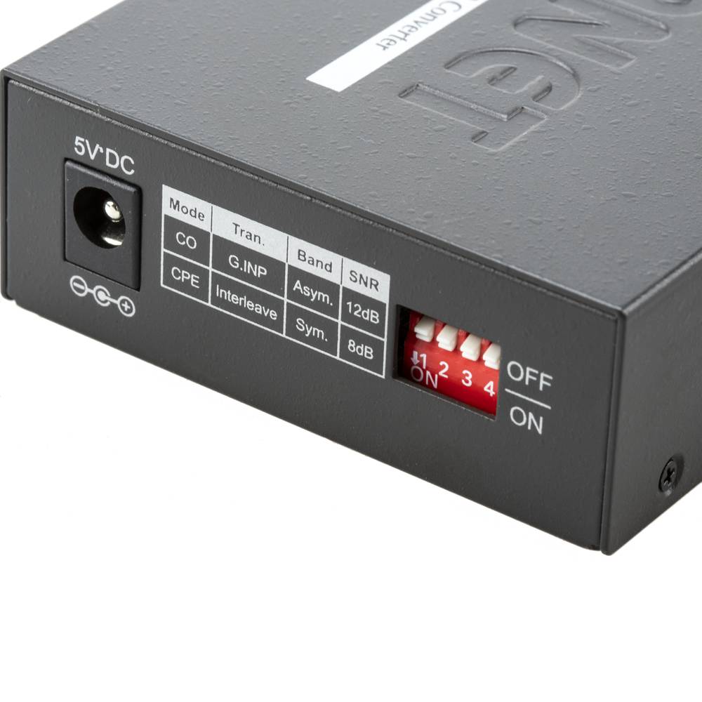
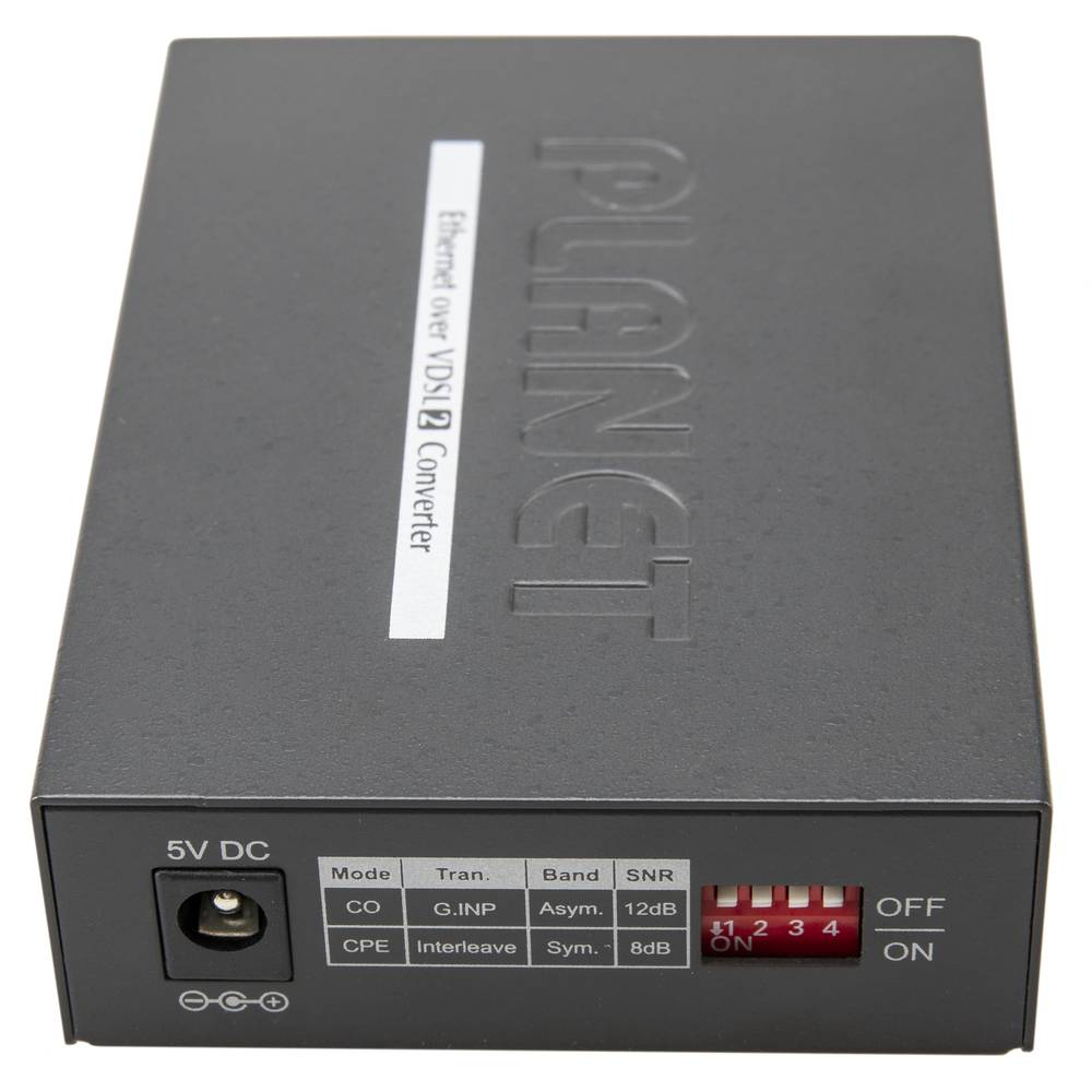
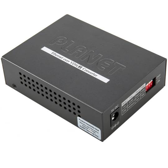
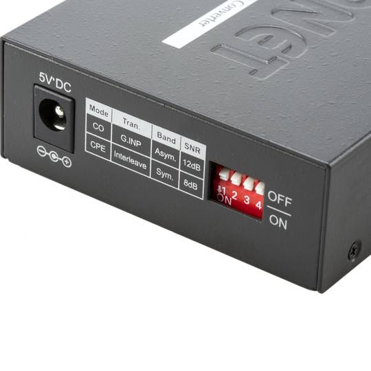
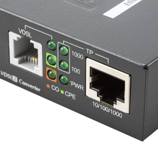
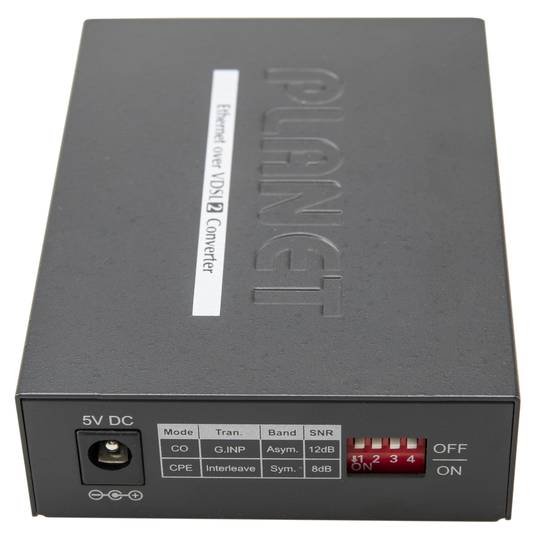
- VDSL2 solution with CO and CPE operations selectable by DIP switch.
- VDSL-DMT ITU-T G.993.1 VDSL, ITU-T G.997.1 and ITU-T G.993.2 VDSL2 with support profile 17a.
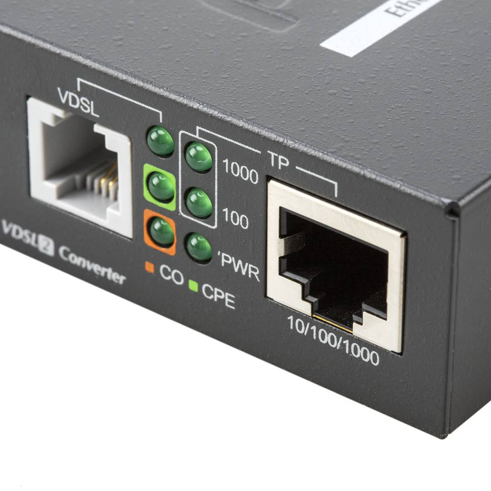
- LED indicators of status, operation and speed.
- Size: 26 x 70 x 97 mm.
![play_button]() Watch video
Watch video
More info
PVP
€211.58
Price including VAT:
€260.24
PVD
€190.76
PVP: Retail price.
Check conditions.
PVP: Sale price to distributors.
Check conditions.
warranty
returns
safe
Specifications
- LAN TCP / IP 10/100 Mbps to VDSL2 converter
- VDSL2 solution with CO and CPE operations selectable by DIP switch.
- VDSL-DMT ITU-T G.993.1 VDSL, ITU-T G.997.1 and ITU-T G.993.2 VDSL2 with support profile 17a.
- LED indicators of status, operation and speed.
- Size: 26 x 70 x 97 mm.
More info
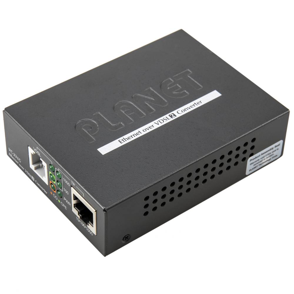
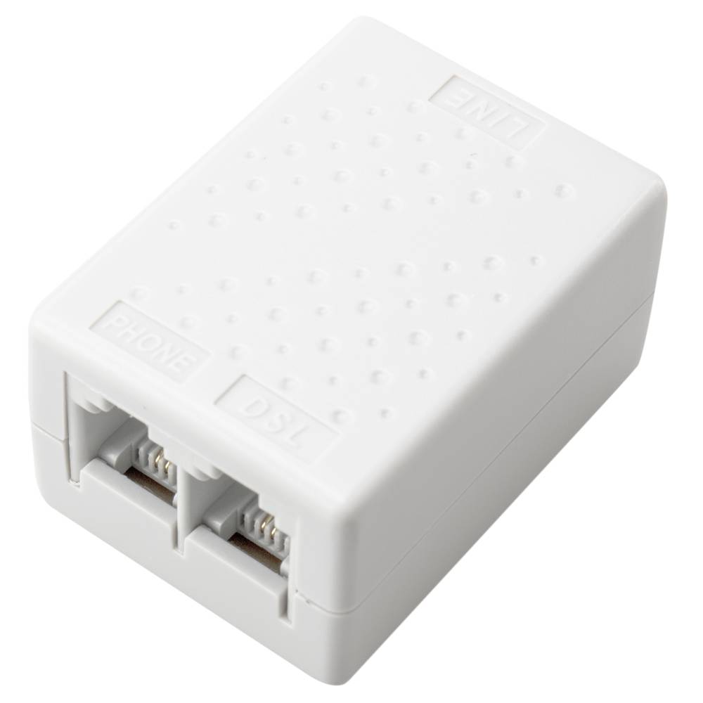
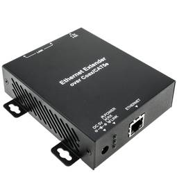
LAN TCP / IP 10/100 Mbps to VDSL2 converter. The VDSL2 technology allows data transport using 2-wire telephone cables (already installed or not) at a maximum distance of 1600 m. By means of a 2-wire telephone cable, data and voice signals can be transported simultaneously and without interference. It is a small module that has 2 RJ11-Female connectors (IN / OUT for the pass through in the case of using an existing telephone installation). It has an RJ45 connector for connection to the LAN 10 / 100Mbps TCP / IP that we want to convert to VDSL2.
LAN to LAN configuration (point to point)
It would be an extension of the Ethernet network cable at a maximum distance of up to 1 km. 2 modules are required installed one on each end and interconnected by telephone cable through which the VDSL2 signal is transmitted. Multi-LAN configuration (multi-point)
It would require a single module and act as a converter from VDSL2 to LAN. It would connect to a telephone cable that carries VDSL2 signal that can come from a router, VDSL2 switch, etc.
Asymmetric VDSL2 Transmission Speed
- 200m: 100/55 Mbps. 400m: 90/50 Mbps.
- 600m: 70/40 Mbps. 800m: 60/25 Mbps.
- 1000m: 45/15 Mbps. 1200m: 35/10 Mbps.
- 1400m: 30/6 Mbps. 1600m: 25/4 Mbps.
Symmetric VDSL2 Transmission Rate
- 200 / 400m: 90/90 Mbps
- 600m: 70/70 Mbps. 800m: 55/50 Mbps.
- 1000m: 40/35 Mbps. 1200m: 30/25 Mbps.
- 1400m: 25/20 Mbps. 1600m: 20/15 Mbps.
Specifications
- LAN TCP / IP 10/100 Mbps to VDSL2 converter
- VDSL2 solution with CO and CPE operations selectable by DIP switch.
- VDSL-DMT ITU-T G.993.1 VDSL, ITU-T G.997.1 and ITU-T G.993.2 VDSL2 with support profile 17a.
- LED indicators of status, operation and speed.
- Size: 26 x 70 x 97 mm.
- Gross Weight: 630 g
- Product size (width x depth x height): 9.5 x 7.0 x 2.5 cm
- Number of packages: 1
- Packages size: 28.5 x 14.0 x 6.8 cm
Technical terms
- RJ11
- RJ45
RJ11
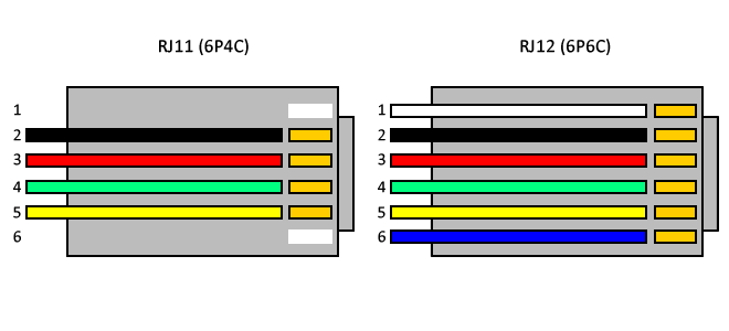
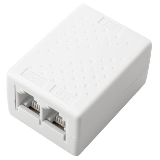
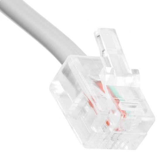
The RJ-11 is mainly used to link telephone networks connector. It is small and has four contacts measures to support 4-way 2 cables. It is the most widely used globally for connecting conventional telephones, which generally tend to use only the two central threads to a single line or a twisted pair connector. And the four wires are used only for telephony equipment special using double line or two telephone pairs. After crimp the cable, it is almost impossible to disarm the RJ-11 without causing its deactivation.
