09/25/2025 3:35 a.m.
http://34.77.62.133/en/products/ubiquiti-er-4-edge-router-4p-edgemax-router-UI153/
http://34.77.62.133/en/products/ubiquiti-er-4-edge-router-4p-edgemax-router-UI153/
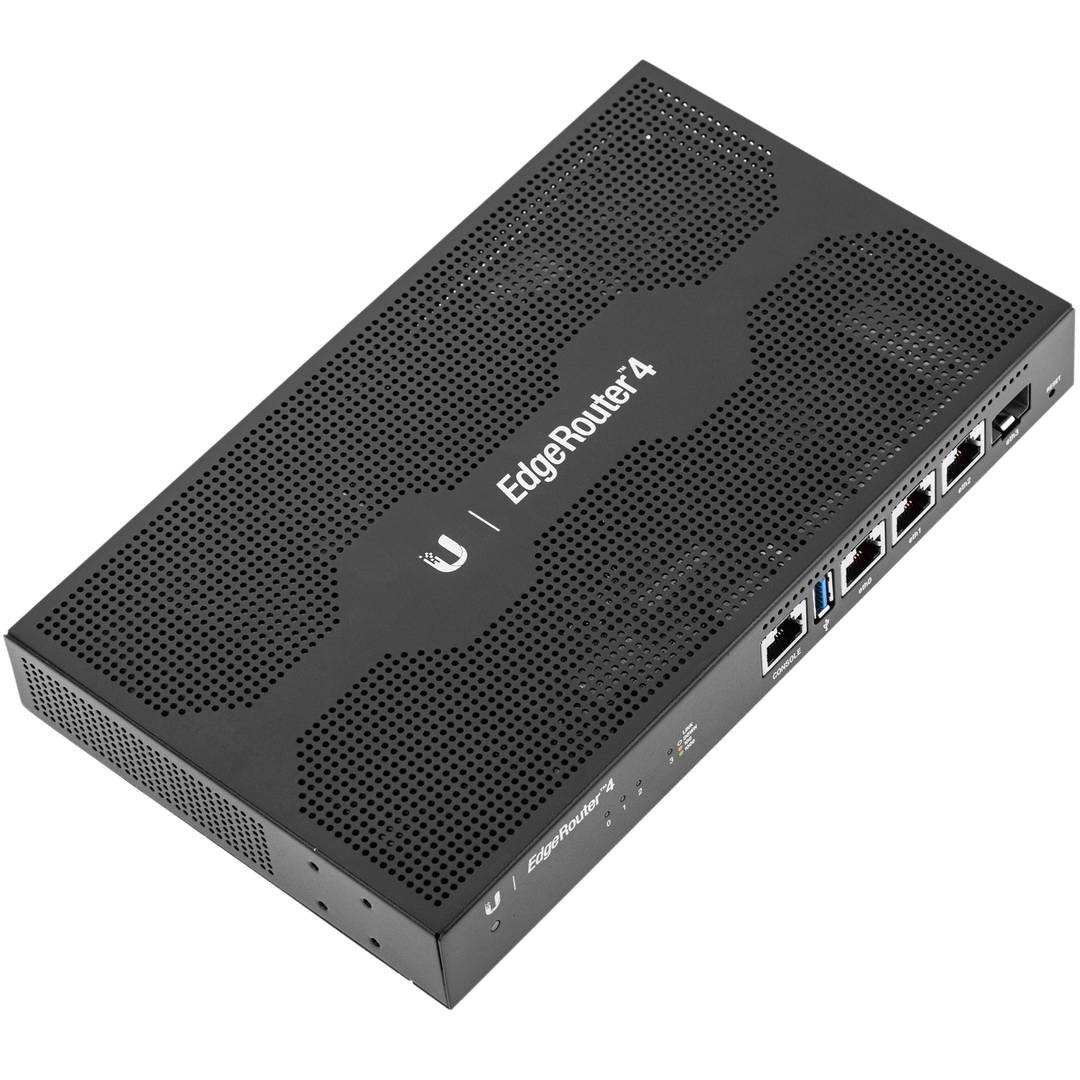


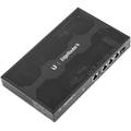
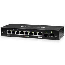
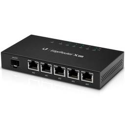
Ubiquiti ER-4 Edge Router 4P Edgemax Router
Ubiquiti ER-4 Edge Router 4P Edgemax Router
REF: UI153


Specifications
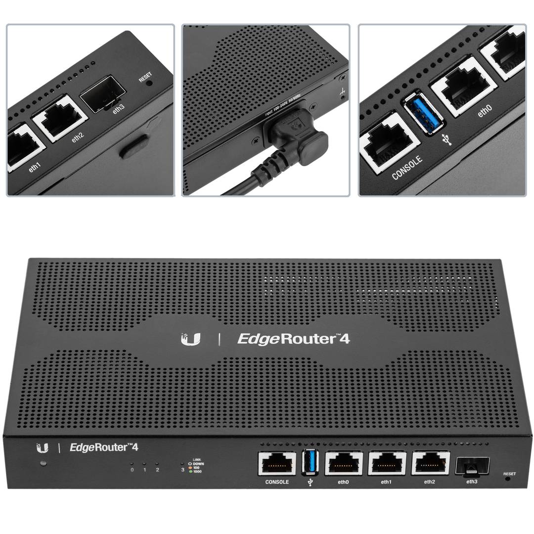
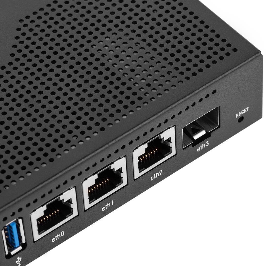
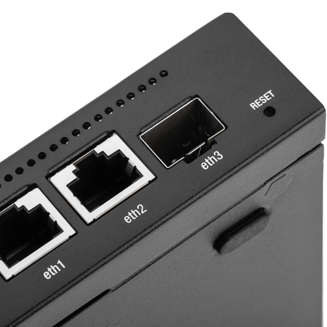
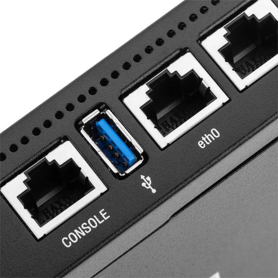
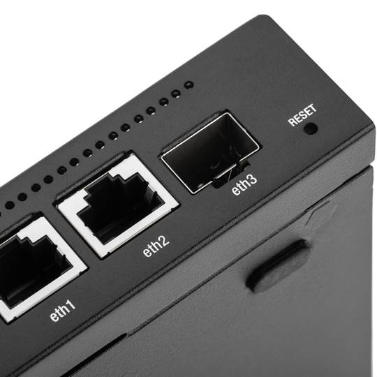
- 3-Port RJ45 Gigabit Router with 1 SFP Port for Fiber Uplink.
- (3) Gigabit RJ45 ports.
- (1) Gigabit SFP port.
- 3.4 million packets per second for 64-byte packets.
- 4 Gbps for packets of 128 bytes or more.
PVP
€189.09
Price including VAT:
€232.58
PVD
€181.82
PVP: Retail price.
Check conditions.
PVP: Sale price to distributors.
Check conditions.
warranty
returns
safe
Specifications
- 3-Port RJ45 Gigabit Router with 1 SFP Port for Fiber Uplink.
- (3) Gigabit RJ45 ports.
- (1) Gigabit SFP port.
- 3.4 million packets per second for 64-byte packets.
- 4 Gbps for packets of 128 bytes or more.
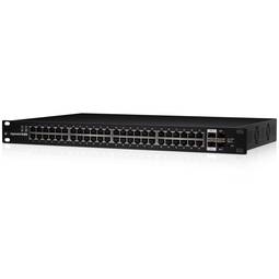
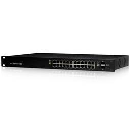
Related products


More info
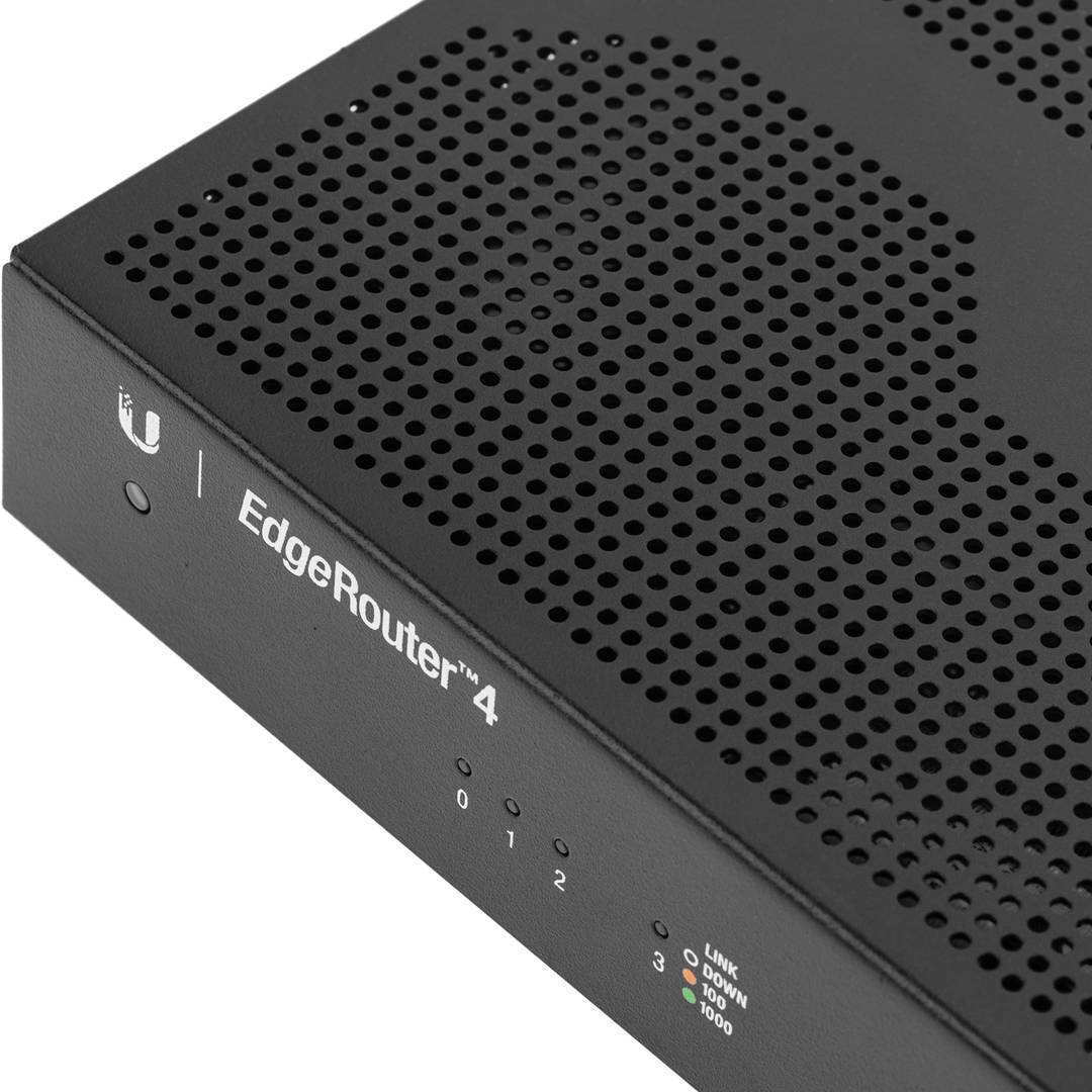
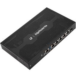
Ubiquiti Networks brand router model ER-4. Gigabit router with 3 RJ45 ports. Ideal device for a home network distribution system. Device capable of transmitting high amounts of information.
Specifications
Specifications
- 3-Port RJ45 Gigabit Router with 1 SFP Port for Fiber Uplink.
- (3) Gigabit RJ45 ports.
- (1) Gigabit SFP port.
- 3.4 million packets per second for 64-byte packets.
- 4 Gbps for packets of 128 bytes or more.
- Management protocols UNMS, CLI, SNMP, NetFlow, LLDP, NTP.
- Supported security algorithms IPSEC, SNMP, SSH.
- Gross Weight: 2.0 kg
- Product size (width x depth x height): 22.9 x 13.7 x 3.1 cm
- Number of packages: 1
- Packages size: 34.5 x 19.0 x 6.5 cm
- Master-pack: 1
Technical terms
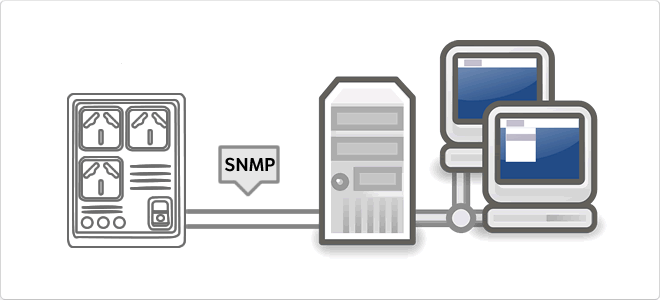
- SNMP
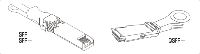
- SFP
- Gbps
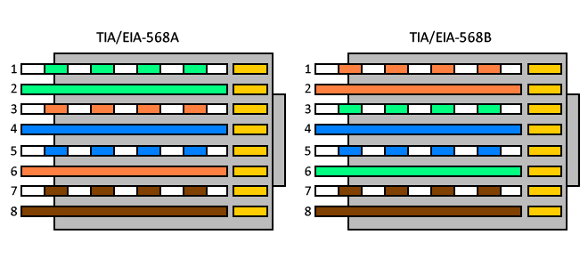
- RJ45
SNMP
The Simple Network Management Protocol, or SNMP (English Simple Network Management Protocol) is a protocol for the application layer that facilitates the exchange of management information between network devices. It allows administrators to monitor network performance, find and solve problems, and plan for growth. In an attempt to explain in a simple way, we could imagine that instala card using SNMP to monitor a UPS on a network.