09/29/2025 10:01 a.m.
http://34.77.62.133/en/products/usb-20-adapter-101001000-mbps-gigabit-ethernet-gb-RA014/
http://34.77.62.133/en/products/usb-20-adapter-101001000-mbps-gigabit-ethernet-gb-RA014/

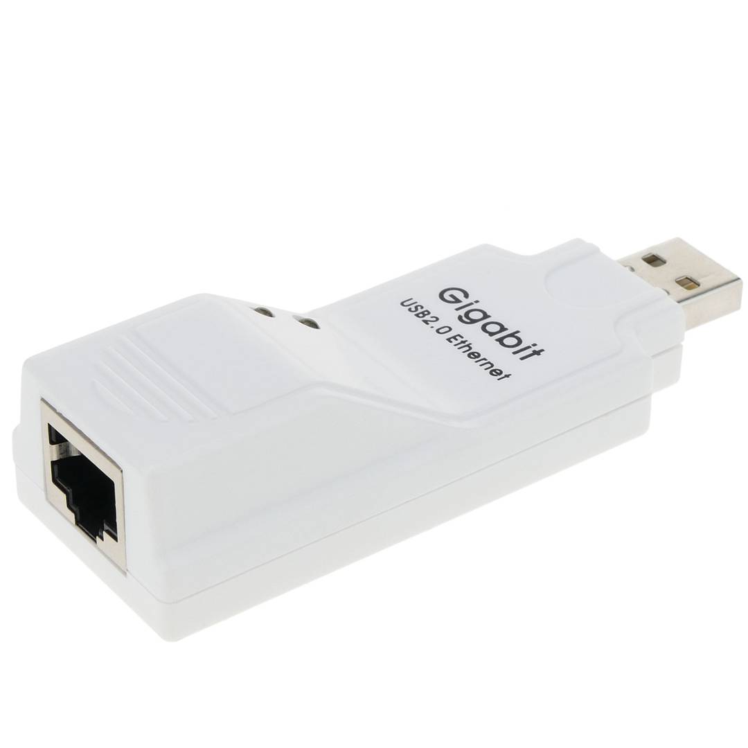
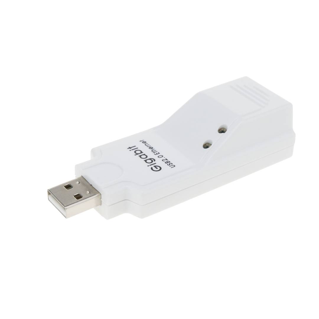

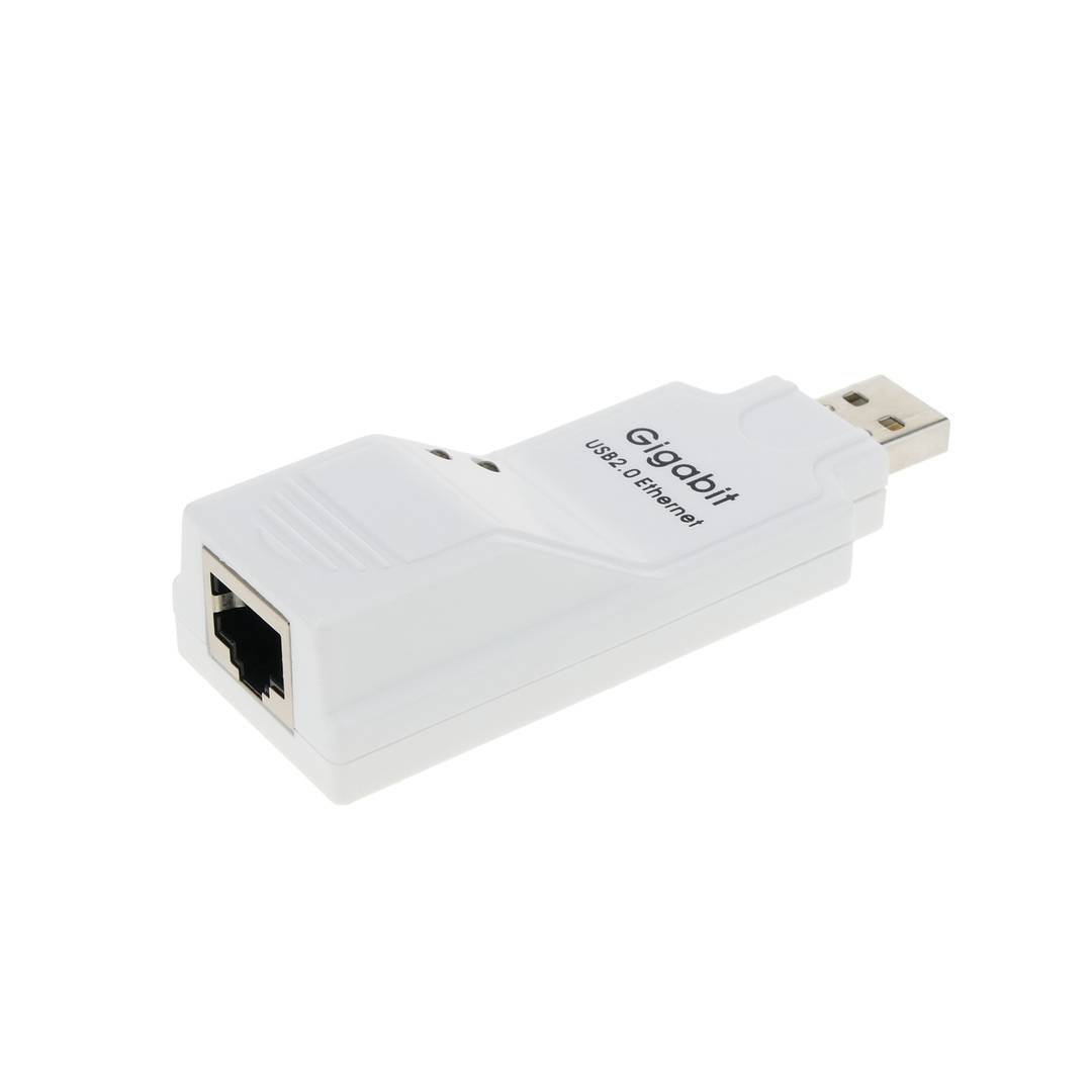
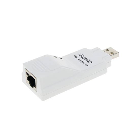
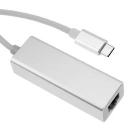
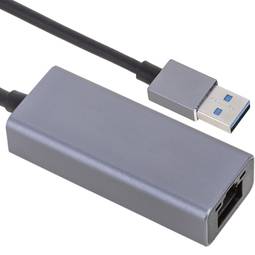
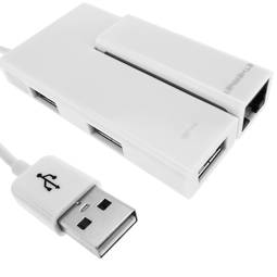
USB 2.0 adapter 10/100/1000 Mbps Gigabit Ethernet Gb


USB 2.0 adapter 10/100/1000 Mbps Gigabit Ethernet Gb
REF: RA014


OUTLET
Specifications
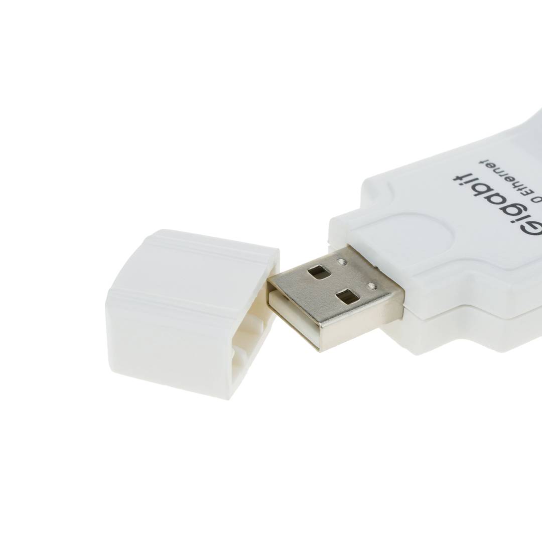
- Compatible USB 1.1 and 2.0.
- It is powered through the USB port.
- Supports half/full duplex operations.
- Compatible with Windows environments.
- LED indicators of Link, Activity andSpeed.
PVP
€8.02
€6.82
Price including VAT:
€8.39
PVD
€7.05
€5.99
PVP: Retail price.
Check conditions.
PVP: Sale price to distributors.
Check conditions.
warranty
returns
OUTLET
Specifications
- Compatible USB 1.1 and 2.0.
- It is powered through the USB port.
- Supports half/full duplex operations.
- Compatible with Windows environments.
- LED indicators of Link, Activity andSpeed.
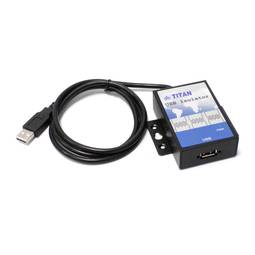
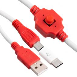
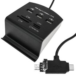
Related products
Keywords
Did not find what you were looking for? These topic could help you
More info
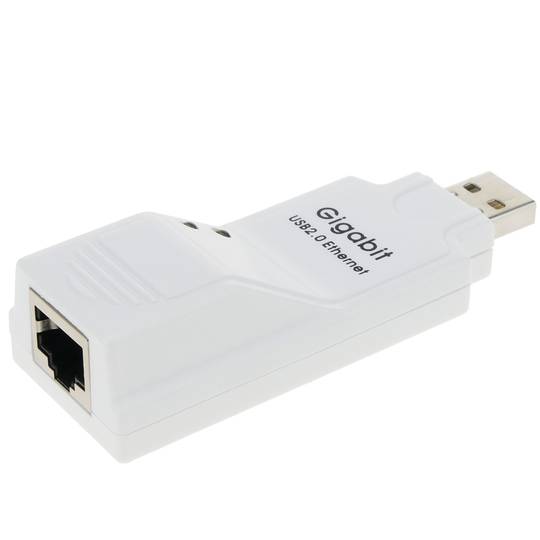
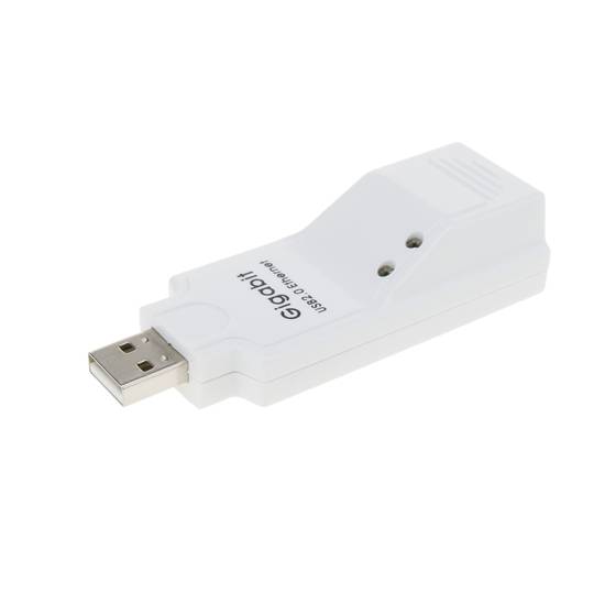
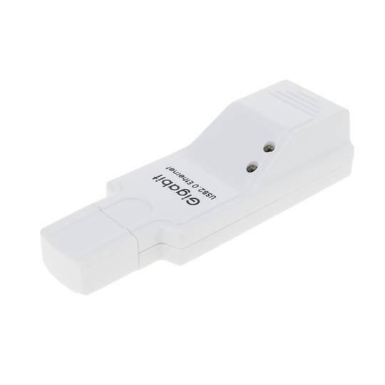
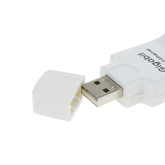
USB 2.0 to Gigabit Ethernet Adapter (10/100/1000 Mbps). It allows to have a connection of 1Gb without needing abrir the computer because it is enough with connector this adapter to the USB port.
Specifications
Specifications
- Compatible USB 1.1 and 2.0.
- It is powered through the USB port.
- Supports half/full duplex operations.
- Compatible with Windows environments.
- LED indicators of Link, Activity andSpeed.
- Automatic negotiation of speed.
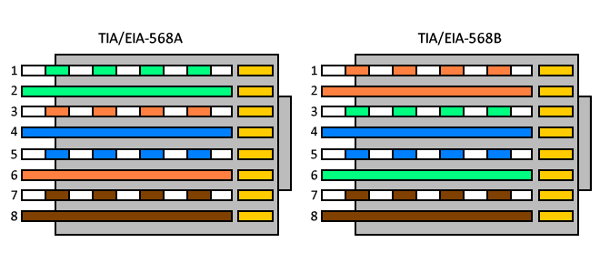
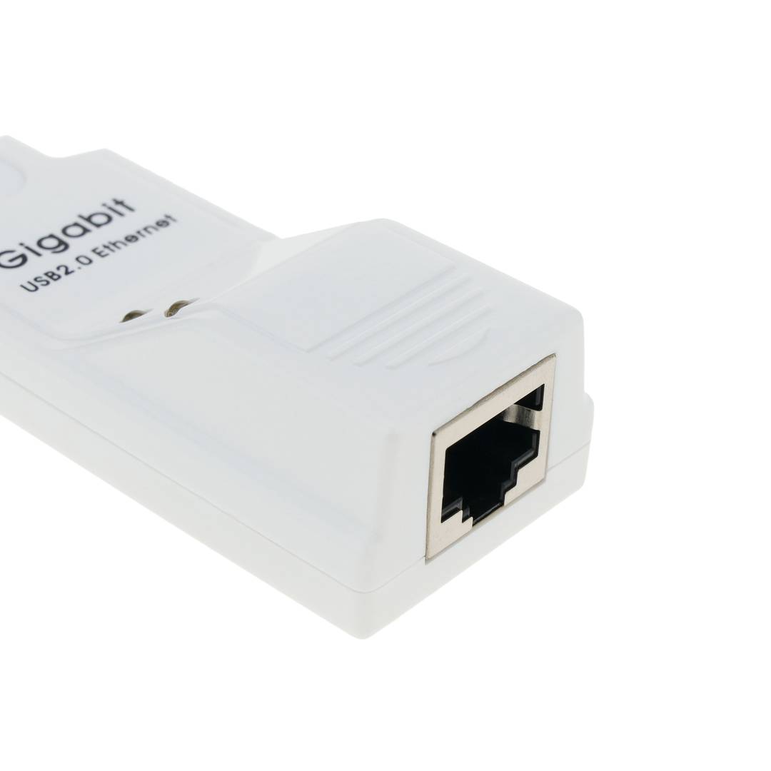
- RJ45 connector compatible with MDIX car.
- SRAM of 20Kb for Rx packages and 20Kb for Tx packages.
- Compatible IEEE 802.3 10Base-T, 802.3u 100Base-Tx and 802.3ab 1000Base-T.
- Module size: 89 x 32 x 16 mm.
- Consumption: 5 VDC at 530 mA.
- Gross Weight: 100 g
- Number of packages: 1
- Master-pack: 50
Technical terms
- USB
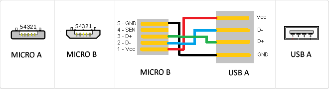
- MicroUSB
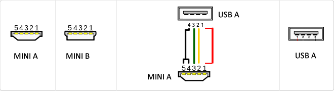
- Mini USB
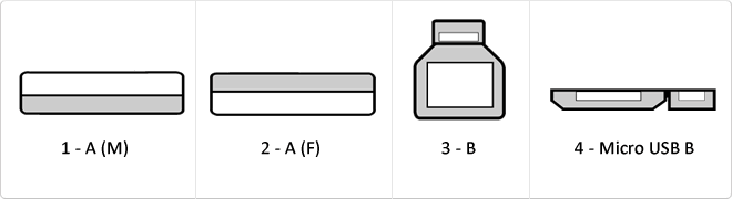
- USB 3.0
- MDIX
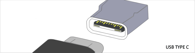
- Reversible USB Type-C
- Gbps
- VDC
- RJ45
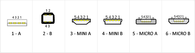
USB
The USB (Universal Serial Bus) is a standard that defines the cables, connectors and used a bus to connect, communicate, computers, peripherals and electronic devices protocols Transmission Rates Low speed (USB 1.0). Transfer rate up to 1.5 Mbit/s (188 kB/s) used in keyboard, mouse ... transfer rate up to 12 Mbit/s (1.5 MB/s) High Speed ??(USB 2.0): Rate transferencia up to 480 Mbit/s (60 MB/s) SuperSpeed ??(USB 3.0) transfer rate up to 4.8 Gbit/s (600 MB/s) Connector Types 1 - USB type A (4 pin) 2. - USB type B (4 pin) 3 - Mini A (5-pin) 4 - Mini B (5-pin) 5 - Micro A (5-pin) 6 - Micro B (5-pin)